
So, you’re a theatrical equipment integrator, and over the last 20 years, you and your engineering department have built up a robust library of AutoCAD blocks, and you have settled into a solid documentation workflow. Now, the construction manager on your newest project is telling you that your equipment needs to be included in a BIM (Revit) model. Or perhaps you are a theatrical equipment manufacturer, and you are getting more and more calls recently from architects and consultants asking for your Revit families to use in their designs.
You may not be sure what the CM is asking you to do, but you know enough about BIM and Revit to say, “Sorry…we don’t do that”. You may not know precisely what Revit families are but are confident your company doesn’t have them. You may have 3D CAD blocks or even Solidworks or Inventor files that might be “good enough” to solve the immediate need, but is this the best long-term solution?
The intent of the blog is not to try to convince any company to change their processes or that BIM is the be-all-end-all solution to every construction coordination challenge. Through this and future posts, I hope we can provide some education on the implications of BIM beyond all those pretty images you see in a building model.
So, What is BIM?
BIM, or Building Information Modeling, refers to a digital representation of a building’s physical and functional components. There are hundreds of excellent articles that explain BIM and how it is used in the construction industry – Googling “What is BIM” will give you a plethora of results. One short but rather clever approach from the BIM management platform Plannerly is How to Explain BIM to Your Grandma. The better-defined technical approach can be found in the ISO-19650 standard. Or you can ask ChatGPT to get Ryan Reynolds’ take on it. We do not feel the need to replicate this information when even fake Ryan Reynolds can do it far better.
So, is BIM a fancy way to say, “drawing a building in 3D”? Sure, but only if you think an iPhone is just a phone! Many consider BIM a 3D model of the building from which the 2D pdf plans are created. Or a 3D model that architects and engineers spend thousands of hours toiling over to ensure that sprinkler pipes route around air ducts, only to have the guys on the job site ignore it? Both are accurate, but not complete. Modeling, documentation, and clash detection components are a substantial part of the BIM process. However, there is a bigger picture that we should not ignore.
To start, we note two important points:
- Autodesk Revit is a BIM tool, but it is NOT BIM.
- The 3D geometry that represents the building and its equipment is only one component of a BIM model.
If BIM Isn't Revit, What Is It?
First and foremost, we need to understand the association between BIM and Revit. BIM is a process that encompasses many tools and communication workflows. Revit is a design software and is currently the most widely used modeling software to support a BIM workflow.
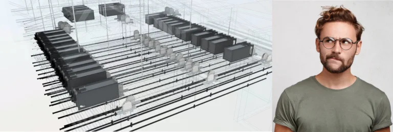
It is common for the I (information) and the M (modeling) to get lost in the BIM conversation. We often think of the model as the virtual 3D geometry of the building. Objects that represent floors, walls, ceilings, structural framing, mechanical ducts, etc., all form the virtual design of a facility. But beyond the physical geometry, the BIM workflow includes modeling for structural analysis, HVAC / Mechanical systems calculations, lighting design modeling, and a host of other non-physical modeling algorithms to aid in both the building design and construction as well as the building operations.
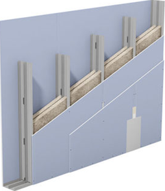
This leads us to the many times overlooked but arguably the most critical component of BIM – Information. Unlike the days of AutoCAD, virtual building models are created from component objects – for example, let’s take a wall. A wall is inserted into a model with its three-dimensional properties: length, height, and thickness. The wall component holds that dimensional information but also much more. For instance, its thickness is derived from its assembly – let’s say a steel stud wall with two layers of 5/8″ gyp board on both sides, painted blue. Using this information, the model can generate material takeoffs and a rendering of the finished product. And these material takeoffs and renderings are “live,” so if that stud and gyp wall needs to change to a CMU construction, the takeoff and rendering changes as well.
The connection of the wall’s “information” doesn’t stop there. The wall’s height is connected to the floor above, which has a thickness of, let’s say, 14”. If the floor thickness changes, the wall height automatically changes to compensate for the new thickness, which adjusts the takeoffs and renderings accordingly.
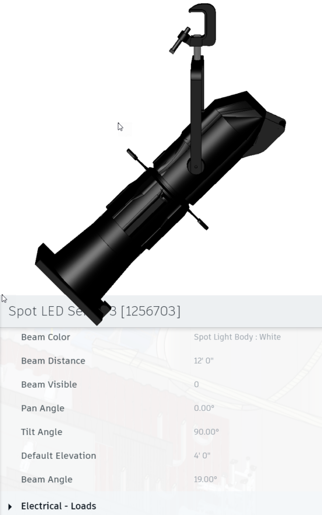
Similarly, we can look at components in the building beyond their geometry. Consider a theatrical lighting fixture placed in the virtual space in a fixed installation. Beyond its three-dimensional property information, this fixture has an electrical connection that draws power that can be used for calculations on the electrical system. The light beam has a spread and output for use in lighting calculations. The manufacturer and model number of the fixture, as well as other product-specific details, can be included to allow for scheduling and procurement.
These are examples of how the information is used during the design and construction process. But in addition, the same data is inherently embedded in the model that can be turned over to the owner for operational purposes. At its most simplistic level, the fixture becomes part of an asset tracking database, where serial numbers have been entered prior to turnover. Or the fixture includes dimming control or IoT (Internet of Things) integrations to supply energy monitoring and/or control via large-scale Building Management Systems and lifecycle analysis.
Ok - But We Work in the REAL World, Not Computer Models
I have a friend who owns a theater equipment integration company whom I respect tremendously. I knew when I proposed the idea of Performance BIM, he would be our very last client, if ever at all. In his eyes, the BIM process wastes time and money because the trades working on-site don’t install per the model. The information can be better communicated through drawings, conversations, and discussions/coordination. We can agree to disagree, but the root of this concern is not unfounded.
Most BIM processes fail when they are either approached as an afterthought or, most often, when the process only includes part of the team. Seasoned architects and engineers may miss critical details because the models were developed by younger, more tech-savvy modelers, who are less experienced designers. The engineering team may labor over BIM model coordination for months, only to omit the trade superintendent from the process, thus missing the critical connection between the virtual model and the active job site. Automated clash detection systems process design models and spit out a lengthy report of the “issues” but don’t account for basic constructability.
These are not problems with the concept of BIM, nor even with the software tools, but with the workflow used in the BIM process for a specific project. BIM is fundamentally about communication. The way to avoid disconnection is to engage all trade partners throughout the process. This means ensuring that we are active and involved in the process and engaging our site foreman in critical meetings. It may also mean pushing back on lengthy general BIM coordination meetings and requesting to attend only targeted meetings.
Responding to a clash detection report is only a part of the process. Understanding the virtual design process and navigating BIM models confidently helps to proactively identify issues rather than simply reacting to them. Even if not working directly in a 3D model, having the ability to export building plans and sections can help ensure the equipment placed in the live model are wholly integrated and coordinated with submittals to avoid inconsistencies.
While this may mean changing the documentation process, for many, the process can be iterative. Learning new software is time consuming, and it’s the last thing we want to do when our focus is already spread too thin on project work. Taking a bit of time to virtually walk around a project on an ACC (Autodesk Construction Cloud) site for project can be useful. Getting a copy of Autodesk Revit LT in order to take export plans can save CAD time redrawing the building. Partnering with a BIM consulting firm (yes – Performance BIM does that!) for a project to incorporate equipment into a 3D model can help to build the tools and documentation standards that can initially be overwhelming.
What Next?
A BIM workflow isn’t necessary for every project. But the requirement is not going away. When Butch and I started developing our workflows at Theatre Consultants Collaborative in 2018, we had one project pushing us into working in Revit. By 2020, almost every new project contractually required us to work in Revit. In the last year, Performance BIM has seen the requests for specialty construction trades to provide their equipment in an overall BIM model rise substantially. The key is having a plan in place – whether hiring / training someone internally to manage a BIM process or having an outside vendor or subcontractor available on call to provide the integration.
Our next few articles in this series start to address the questions of beginning the process and making it useful.